Centrifugal Pumps
Products
Centrifugal Pumps
Our centrifugal pumps operate by developing high flow speeds and turning that speed into pressure in a decreasing flow rate. Its installation is vertical and has a hydraulic seal system allowing the use of the unit empty of fluid without causing damages because there is no friction among its parts (like the mechanical sealed pump, stuffing box, etc.).
For the correct choosing of the material you need to bear in mind: – the kind of fluid to pump, – flow, -temperature of the fluid, viscosity, -unload pressure, -anpa available. Our equipment fits Chemical Industry, Petrochemical, Pharmaceutical, Mining, Fishing, Leather, Paper, Food, Cosmetology, etc.
General characteristics:
Installation: Vertical
Component: Polypropylene (see chemical resistance table)
Type of Seal: Hydraulic seal
Maximum Working Temperature: 194° F
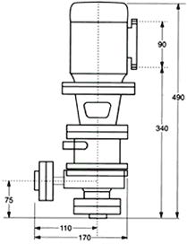
Electrical engine: 0,5 HP; 2800 RPM; 220/380 V; 50 Hz; Protection IP 55;
Metal lined 100%
Suction lift: 1″ Ø
Pumping: 1/2″ Ø
Installation: Under fluid level
Flow curves
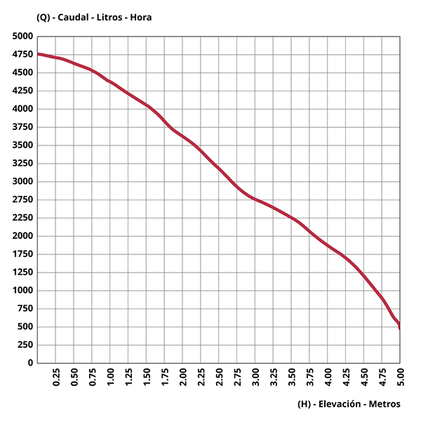
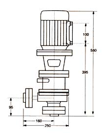
Electrical engine: 1 HP; 2800 RPM; 220/380 V; 50 Hz; Protection IP 55; Metal lined 100%
Suction lift: 1 1/2″ Ø
Pumping: 1″ Ø
Installation: RZ-1-E under fluid level / RZ-1-R Over fluid level
Flow curves

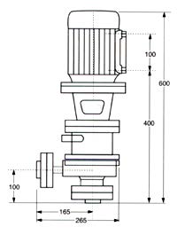
Electrical engine: 2 HP; 2800 RPM; 220/380 V; 50 Hz; Protection IP 55; Metal lined 100%
Suction lift: 1 1/2″ Ø
Pumping: 1″ Ø
Installation: RZ-3-E under fluid level / RZ-3-R Over fluid level
Flow curves


Electrical engine: 10 HP; 2800 RPM; 220/660 V; 50 Hz; Protection IP 55; Metal lined 100%
Suction lift: 2″ Ø
Pumping: 1 1/2″ Ø
Installation: RZ-4-E under fluid level / RZ-4-R Over fluid level
Flow curves
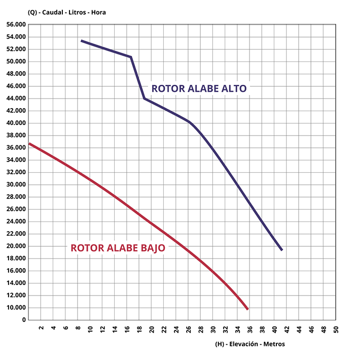

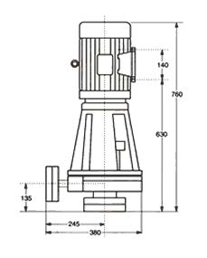
Electrical engine: 5.5 HP; 1500 RPM; 380/660 V; 50 Hz; Protection IP 55; Metal lined 100%
Suction lift: 3″ Ø
Pumping: 2″ Ø
Installation: RZ-BE-1-E Under fluid level / RZ-BE-1-R Over fluid level
Flow curves

Electrical engine: 5.5 HP; 2800 RPM; 380/660 V; 50 Hz; Protection IP 55; Metal lined 100%
Suction lift: 2″ Ø
Pumping: 1 1/2″ Ø
Installation: RB-5-E under fluid level / RB-5-R Over fluid level
Flow curves
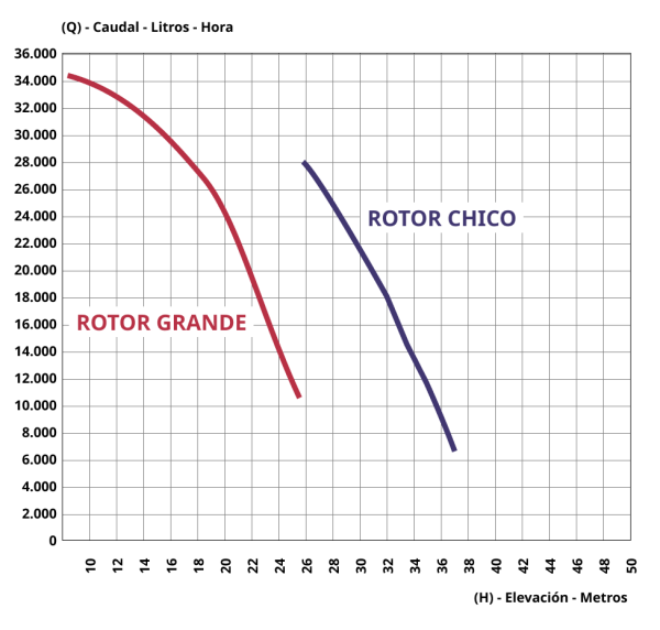
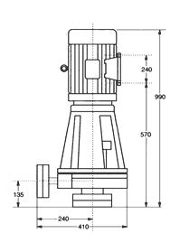
Electrical engine: 30 HP; 2800 RPM; 380/660 V; 50 Hz; Protection IP 55; Metal lined 100%
Suction lift: 3″ Ø
Pumping: 2″ Ø
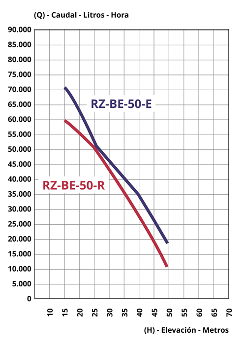
Installation: RZ-BE-50-E Under fluid level / RZ-BE-50-R Over fluid level
Flow curves
PUMP EXPLODED DRAWING (MS-E ; RZ-1 ; RZ-3 E y R)

PUMP EXPLODED DRAWING (RZ-BE-1 ; RZ-BE-50 ; RZ-4 ; RB-5)

INSTALLATION DRAWINGS
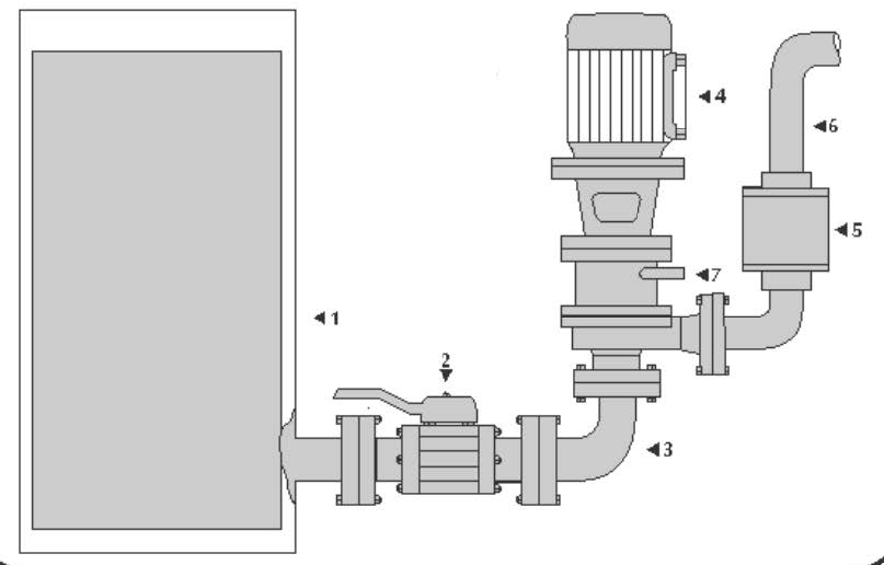
- Place the pump unit as shown in the picture.
- A vertical check valve should be placed on one end of the discharge pipe.
- Put a ball valve on the discharge pipe whenever you need to adjust the liquid flow.
- Look at the rotation direction of the pump.
HOW TO START THE PUMB
- Start it
- Open the pass valve N°2 and N°5
HOW TO STOP THE PUMP
- Close the pass valve N°2 and N°5. 2. 1. 2. 3. 4. 5. 6. 7.
- Cut the electrical flow of the pump N°4.
OBSERVATIONS
Remember to keep valves N°2 and N°5 closed when the pump is not working, otherwise the flow will be discharged through pipe No7.
- Container
- Ball valve
- Suction pipe
- Vertical centrifugal pipe
- Ball or check valve
- Discharge pipe
- Level pipe hydraulic Chamber
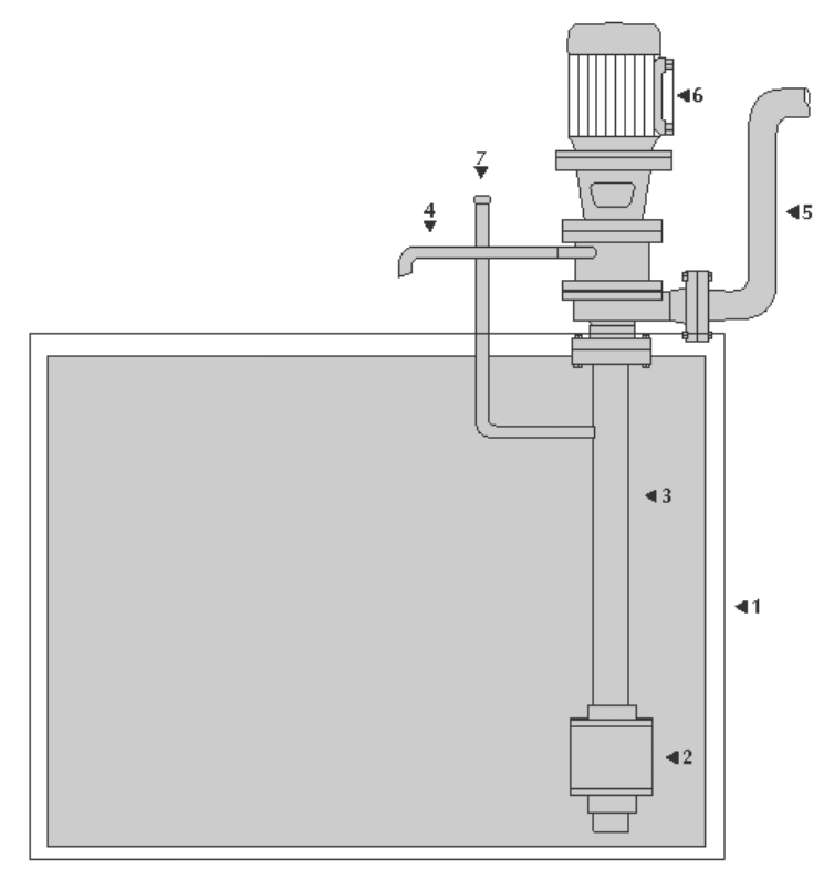
HOW TO INSTALL THE PUMP
- Place the pump unit, over the surface of the liquid, the level pipe N°4 over the hydraulic chamber, discharge the liquid leftovers produced in the chamber in the container as it is shown in the picture.
- In all cases, the discharge pipe N°5 should be placed at least a meter up 2. 1. 2. 3. 1. 2. 3. 4. 5. 6. 7. as shown in the picture.
HOW TO PRIME AND START THE PUMP
- Look at the rotation direction of the pump.
- Put off the bung from the priming pipe No7, fill it with liquid until it spills some through the level pipe of the hydraulic pump N°4.
- Start it, it will have a good and permanent performance.
OBSERVATIONS
While the pump is working you will see a steady discharge In the container N°1.
- Container
- Threaded check valve
- Suction priming pipe
- Level pipe bydraulic chamber
- Discharge pipe
- Vertical centrifugal pump
- Miming pipe Bung
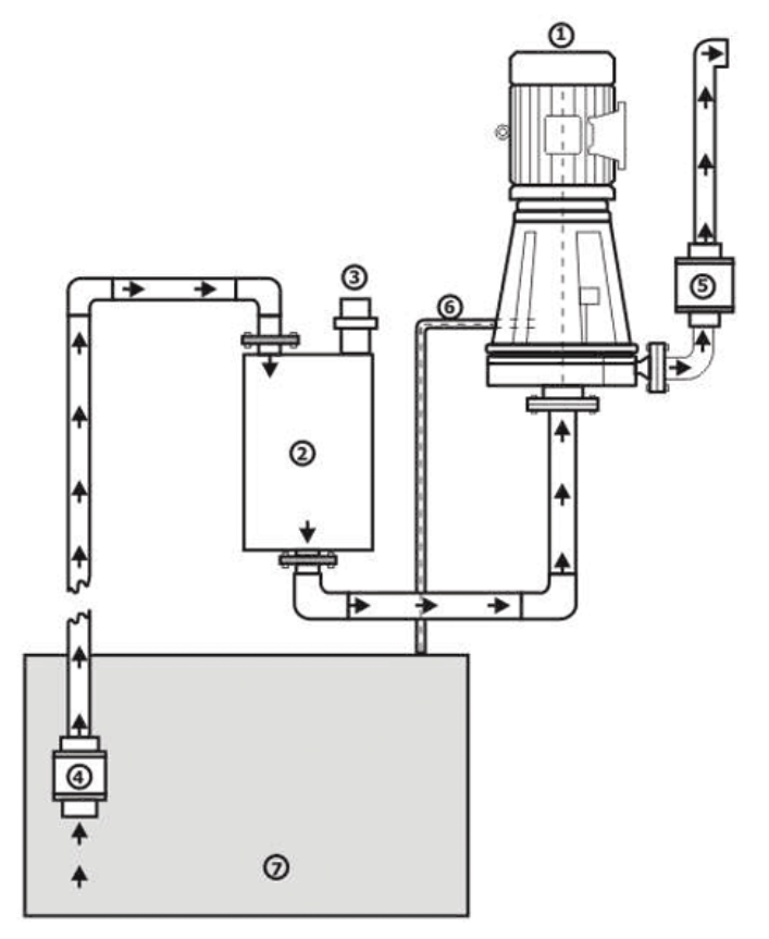
HOW TO INSTALL THE VERTICAL HYDRAULIC SEALED PUMP MODEL R
- Place the pump set over the level of the liquid to be pumped.
- The hydraulic chamber level pipe n°6 will have to pour the surplus liquid, produced inside the chamber as shown in the scheme, into the container n°7.
HOW TO PRIME, START AND STOP THE PUMP:
- Check the rotation direction of the pump before starting it. (Seen from above it has to rotate clockwise).
- Take out the bung n°3 and fill the container up to the top.
- Start the pump.
- To stop the pump cut its electric flow.
OBSERVATIONS
A constant pouring will be observed inside the container no7 through the pipe n°6 while the pump is running.
- Vertical centrifugal pump.
- Self-priming tank with a capacity of 50 liters. Bung.
- Threaded check valve.
- Threaded check valve.
- Hydraulic seal pouring pipe.
- Liquid container.
Contact Bomplast
Address
Fournier 2653/55 (C1437DCK), Autonomous City of Buenos Aires, Argentine Republic
Phone and Fax
(54-11) 4922-8480
(54-11) 4925-5647
info@bomplast.com.ar
